There's an interesting section in the EM Gauge Society manual looking at prototypical railway goods handling in the 1950s. I read it with interest as I'm keen to find out as much as possible about prototype operating practise - both to inform the way I construct the model and also, later, the way I operate it.
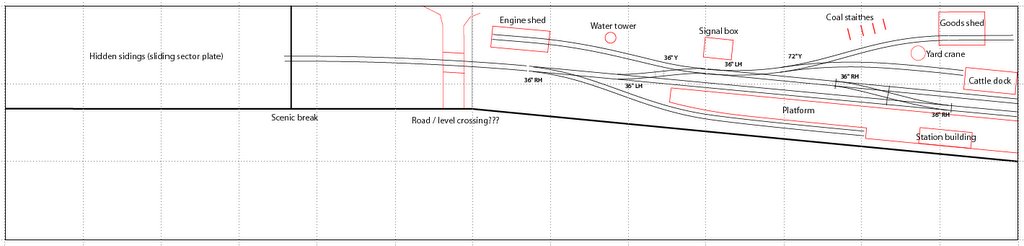
Currently my plan, as the track plan shows, is to have a simple two-road goods yard adjacent to the station platform. My initial thoughts were that I would incorporate a goods shed, some coal stacks, and a cattle dock, with a yard crane for general unloading. The question is where to position these things in a way that allows for prototypically correct operation.
I had sketched in on my plans to have the coal stacks adjacent to the goods shed road, but I'm wondering how realistic this is - I don't know how long coal wagons would be left here for unloading comparative to vans in the goods shed, or on the other hand whether goods sheds were still used for unloading of railway vehicles by this stage?
Is the positioning of the cattle dock adjacent to the loop spur a realistic location? I have seen similar positionings on prototype track plans of terminus stations. Were cattle still being transported by rail in the 50s/60s?
Basically, there are a lot of details I still need to find out about before I start attacking the model. One thing I am aware of is that the yard sidings need to be spaced far enough apart to allow vehicle access between them for loading and unloading. I need to take this into account when laying the track.
I'm also still concerned that the goods yard may look a little cramped as laid out on the track plan. Ideally I'd like the yard entrance to be moved further back along the approach line, but this also means pushing back the engine shed, and so on, which encroaches on the second basebaord, means more tracks crossing the baseboard join, and also reduces the perceived lenth of running line from the fiddle yard to the station throat. I know it's got to be a compromise - I don't want the entire layout to just be station without any 'run-in' but at the same time I don't want things to look artificially cramped. (Mind you, compared to the initial ideas I had of squeezing all this onto a 12" wide baseboard this is already spacious!!)
Tuesday, 31 January 2006
Sunday, 29 January 2006
Wiring diagram
 (Click the image to open a larger version in a new window)
The green markings show where power breaks will be introduced with switches to isolate locomotives beyond these locations - namely, at the buffer end of each platform, loop and in the shed road. The latter will have two breaks allowing up to three locos to be stored at any one time (whether there will ever be a needed is another matter although two is likely).
As far as I can see, turnouts 'F' and 'G' must be electrically (and operationally) interlinked so that there is no possibility of a short-circuit developing. I can't see any other potential problem areas. From a prototype operational point of view, I'm not sure also whether 'B' and 'C' would be interlinked to avoid potential accidents! It also makes sense that the main power feed is automatically switched to the shed road when point 'C' is switched to the shed road.
While I'm not yet 100% sure what all this wiring and switches will look like (i.e. how exactly I'll construct it all, connect the power to the rails - including across rail joins etc.) I do anticipate that the electrical switches for each turnout will be linked directly to the point motors, obviating the need for a seperate switch and eliminating the possibility of further accidental short-circuits. I believe the Fulgarex point motors have two built in auxilliary switches which makes them ideal, as well as the fact that their slow motor-driven action (as opposed to the more forceful solenoid type motors from manufacturers such as Peco) is a lot more forgiving on delicate hand-built pointwork! Also, the Fulgarex is apparently smaller than Tortoise motors and slightly cheaper. the only possible drawback I'm aware of is that I've read that the throw of a Fulgarex motor is about 10mm which is a lot more than the actual throw of a turnout. I'm not sure if there has to be some sort of compensation built in or whether the extra distance is taken up by play in the mechanism???
Saturday, 28 January 2006
Track and electrics
I got my EM Gauge Society manual through the post today. I decided to join even though I've decided to build the layout in finescale OO, because I'd heard that the information is worth having anyway. There are 3 rin-binders worth of information sheets covering everything from baseboard construction to prototypical railway operation.
Tonight I've been reading up on electrics and made a start at doing some rough wiring diagrams for the layout - not as easy as I remember it being, partly due to the fact that in my teenage modelling days all the tournouts I used were 'dead frog' which made the whole thing a lot easier to understand!
I'll post a wiring diagram on here soon so those of you with a better understanding of these things can point out all my errors!!
I also ordered some point kits from Mainly Trains yesterday, one from C&L and one from SMP, to get some practise at building track and also to compare the two makes before splashing out on track for the whole layout. I'll report back on progress when they arrive.
Friday, 20 January 2006
Depressed!!!
http://homepage.mac.com/chrisbaker/
Check out the photo gallery ('Gallery') and the close-up photos on the buildings and scenery pages (under 'Construction')...
Check out the photo gallery ('Gallery') and the close-up photos on the buildings and scenery pages (under 'Construction')...
Wednesday, 18 January 2006
Revised track plan
 (Click on the image to see a larger version.)
Not much has changed really since the previous track plan I posted. The main difference is that this one is based on measurements taken from the track templates I got from Marcway so is hopefully to within a few inches of how it will be.
The layout is designed to take a maximum train length of 3 coaches and a tender engine, or equivalent. Both platforms will accomodate 3 coach trains although the main platform is about 5 coach lengths taking into account the run-around facility.
Most of the pointwork is 36" radius with just one 72" radius point in the goods yard.
It's a shame there aren't another 2 or 3 feet of length to play with - it would have been nice to have a little more distance to run the trains before they disappear 'off stage' (replicating some of the scenes around Glastonbury in those S&D photos). I've even semi-seriously contemplated doing away with the hidden sidings altogether for the sake of the additional scenic potential, but for all the advantages from a modelling and photographic perspective, it would make layout operation a hassle - having to constantly lift trains on and off the layout. I guess I'll just have to make the most of the limited space I've got. A well-painted backscene will go a long way to giving a sense of space and of the railway 'in the landscape' which is what I want to acheive. (I think some practise backscene-painting will be in order!)
I'm also wondering whether to do away with the level crossing and to make more of the 2 1/2 feet or so there is beyond the station appraoch and engine shed. This is still enough space to at least suggest at the idea of the railway running through the countryside.
With the inspiration gleaned from those photos I'm thinking of having the track on a slight embankment (which would mean building up the track beds and whole station area using maybe polystyrene tiles or similar) so I can have one of those drainage ditches so typical of the Someset levels. It would only need to be half an inch going by some of those photos.
Monday, 16 January 2006
Somerset & Dorset inspiration
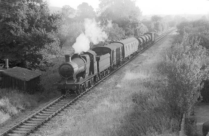 Having already found plenty of inspiration in Chris Nevard's Combwich model (and unashamedly based my layout plan on his, given the similarity in layout dimensions and general prototype era), yesterday afternoonI found myself following web links about the Somerset and Dorset Railway and happened across 3218.co.uk where there is an absolutely superb collection of black & white photos of the last days of steam on the S&D.
There's something incredibly evocative about these images of trains ambling across the Someset levels.
While I don't intend to stick strictly to any exact prototype location with my model, these photos along with the Combwich model have fuelled my imagination enough that I think I'm going to base my model at least loosely on the S&D - albeit a fictional section of line and location and probably with a few items of rolling stock that wouldn't have appeared on the S&D itself.
(Photo copyright Ian D. McKechnie - http://www.3218.co.uk)
Sunday, 15 January 2006
Baseboards and kit-building
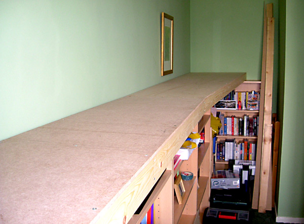 Having had a stack of wood sitting in the spare room for the past week, I finally got round to constructing the basebaords yesterday afternoon. If I were more sensible I probably would have waited for a dry day and done the work outside, but being impatient and slightly impulsive I converted the spare room into an ad hoc workshop!
Several hours and a few blisters and splinters later I had two baseboards sitting atop the shelves, and I'm quite proud of them! They are a simple construction - 9mm MDF tops screwed onto a simple 2 3/4" x 3/4" planed wood framework.
The whole thing is pretty solid and although it's not the lightest thing in the world (it's lighter than chipboard, mind!) it's still portable enough for things like house moves.
The next consideration is how to fasten the two boards together so as the track ends align correctly without the need for rail joiners or removable sections. Also, I need to think about how the backscene will be attached. This will be painted directly onto 18" high hardboard. At the moment I'm tending towards a removable backscene - possibly one that just drops into and lifts out of a 'slot' along the back of the basebaords, meaning it can be painted seperately and also removed easily for moving, with careful scenic work to hide any obvious gaps or joins.
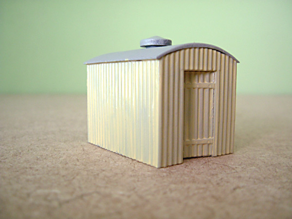 Earlier in the week I bought a couple of Wills plastic kits - just cheap ones - and various paints, brushes etc. I thought it would be good to get a bit of practise at kit building and painting on some small-scale projects before tackling the larger structures that will be needed later. After all, it's been a good 12 or 13 years since I last did any modelling of any sort, and in comparison to what I'm looking to acheieve this time, that was fairly amateur stuff.
Here's a photo of one of the lineside huts. It's not finished yet - it still needs more painting, detailing and weathering. I modified it slightly so the door is slightly open which I think adds a little extra touch of realism. I've used Humbrol grey primer before adding a first coat of cream paint to the walls and door. Actually, the slightly uneven appearance of the single coat of colour is quite good - it gives the appearance of old, worn paintwork rather than it being totally pristine.
Friday, 6 January 2006
Baseboard joins
So the wood for the baseboards has finally been bought. And the realisation has dawned on me that 7 foot and even 6 foot may be too long for a single board if it is to be at all portable. Granted, I don't intend to move the layout often - only if we move house. But I'm seriously wondering whether I should now have four smaller boards instead of two large ones.
The question is this: Will the baseboards be too heavy to move in the event of any future house moves if I leave them as 6' and 7'? I need to take into account the fact that to get a 7' board out of the room will require turning it on it's end, then tilting it to get it through the door, then tipping the whole thing through several different angles to get it down the stairs! All this without knocking anything down (real or model!) in the process! Certainly a two-person job just to do the lifting, and probably another to ensure nothing gets knocked.
If it is doable then I'd rather stick with just the two boards, purely because it's less hassle. If not, then it obviously creates more work in the wiring department and the clever use of scenery to hide the join!
Thursday, 5 January 2006
Yet more thoughts!
The blessing/curse of not getting started building the layout immediately is that there has been plenty of time to think and rethink the track plan etc!
Tomorrow I'm hoping to go and buy the wood for the baseboards etc. so once that's done it's done! But in the meantime I've decided to increase the width to 16", widening to 2' at the station end. This really is the maximum I can do realistically.
I've spent quite a bit of time thinking about the fiddle yard situation and I'm now veering towards the idea of having a very simple sector plate - simply a piece of 3'6" hardboard which moves freely directly on the baseboard. (The main advantage is that no space would be 'wasted' with pointwork - important given the limited space available - I want as much scenic area as possible.) Lining up the rails could be by sight, or else some sort of DIY system if necessary. Electrical current could be switched to the appropriate track via a switch. I think I could fit 4 tracks on the sector plate. This should be adequate, given that some man-handling of stock is going to be inevitable in any case.
Monday, 2 January 2006
Thoughts on prototype operation
One of the things I'm keen to do from the outset is ensure that everything fits reasonably well with prototypical railway practise for the period and location I'm modelling (actually, my current idea is to keep these reasonably broad - rural location jointly operated by the Western and Midland regions, around the 1950s/early 60s... I may get more specific as things develop!), at least to the extent that it satisfies my own desire for realism if not always being strictly accurate down to the last detail. The extent to which you take this is obviously a matter of personal choice.
In coming up with a track plan one of my concerns has been operational realism as well as interest. For example,I knew it was essential from the outset to include a run-around loop on the main platform road so that passenger trains could be pulled into and out of the station. However, I wasn't so sure about the procedure for goods trains. And what about passenger trains using the second platform which doesn't have a run-around loop (a problem of my own making - I wanted a second platform to allow for a little more interest both visually and operationally and already knew from looking at a number of prototype station plans that run-around loops where not provided for all platforms)?
Chris Nevard, creator of Combwich, helpfully provided the information I needed: "All trains coming in would have come into the main platform line, the engine would then run around its train, pull it out again then push into the sidings - this would be the same for the platform without a loop. Lines like this in real life would have only had a few trains a day."
First impressions
I spent Friday and Saturday sawing, drilling, and generally making a fine old mess! The finished product however, is a row of bookshelves running the length of the room providing a 4' high, 13' long 'shelf' for the baseboards to sit on. Quite a satisfying result!
Before building the baseboards I wanted to make sure my plan translated OK into '3D' reality. So I've used a few offcuts from the old shelves to mock up a representation of the baseboard on top of the bookshelves and then used strips of paper to roughly mark out the track plan with various pieces of cardboard and polystyrene packaging representing key features such as the platform, engine shed, etc.
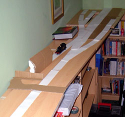 While this might sound uneccesary, it's surprising how different it looks laid out in this way from a 2-dimensional track plan! While the track plan makes it all look quite spacious, in reality there's not really a lot of space to play with. However, I think it still works. One slight adjustment I think I'll make is to increase the width at the station end of the layout to 2 feet. This still fits ok but allows for a little more space in the station and goods yard area.
I'm also thinking of having the platform slightly angled, closer to the line of the front baseboard edge rather than parallel with the back. The again provides a little more space, and also means that the line coming into the station from the fiddle yard follows a single, very gentle curve onto the straight, rather than the slightly unecessary (and unprototypical) S-bend on the original plan.
I've ordered some track templates from Marcway which will help me to plan out the lengths and angles of the turnouts more accurately. Once I've done this and made sure everything still fits I should be in a position to start constructing the baseboards.
Subscribe to:
Posts (Atom)