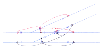
Electronics has never been my strong point, so I'm having to think this through carefully before I do it all wrong! I think the diagram below is correct...
The insulating gaps are represented by the double lines across the rails. The connections between the stock and switch rails will be copper-clad strip stuck to the top of the timbers (with the wire coming up at the side and soldered flat along the top behind the rail out of sight - I think this will work better than what I was trying before), and the connections between the various rails at the crossing will be thin brass strip soldered directly to the bottom of the rails before laying, with the wires soldered to the bottom of this.
I'm not 100% sure if I've got the wiring diagram correct or if there's a simpler way - my thinking is that when the main road is set, the red switch will be 'on' and the black switch 'off', and when the turnout road is set, the black switch will be 'on' and the red switch 'off' (to use complete layman's terms!).
If I've got any of this wrong, can someone please tell me!!!

Matt,
ReplyDeleteA lot will depend on whether you plan to use DCC. If so, I don't think you should have the rails beyond the frog switched - these rails should be live all the time irrespective of the turnout position.
This site is pretty useful:
http://www.proto87.com/turnout-wiring-for-DCC.html
Chris
Hi Chris,
ReplyDeleteI don't plan to use DCC at this stage although it may be something I look into further down the line.
I suppose even using conventional control there's not a lot of point in switching out the power to either set of rails as I won't need to isolate a loco in either siding.
Matt